Additional Links: Midterm Progress | Fabrication Proposal
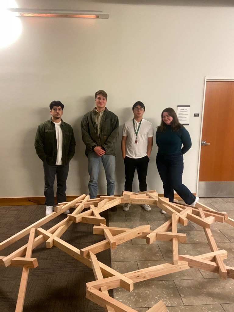
For out final review we presented our model with connection optimizations made for simplified fabrication as we constructed a full scale model. These optimizations came from understanding the relationship of how the diagonal member notches into the horizontal member which was often causing compound angled planes on the bottom of the notch. We found this can be alleviated by notching the the diagonal member all the way through the horizontal member which in term causes a decrease in slope which can be negated by increase the number of sides in the system, thus decreasing the angle that the diagonal intersects the horizontal which is illustrated in the slope diagram video below. A quick function that roughly represents the maximum slope of the given parameters is Max Slope = tan-1((member depth – notch depth)/(extension length * tan(360/number of sides))). With our frame system complete we looked at coverage systems from vining plants to floral panel patterns that follow the visual language of the form.
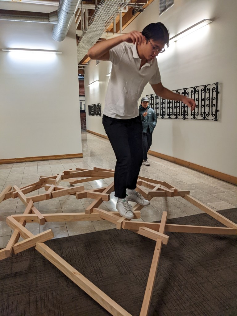
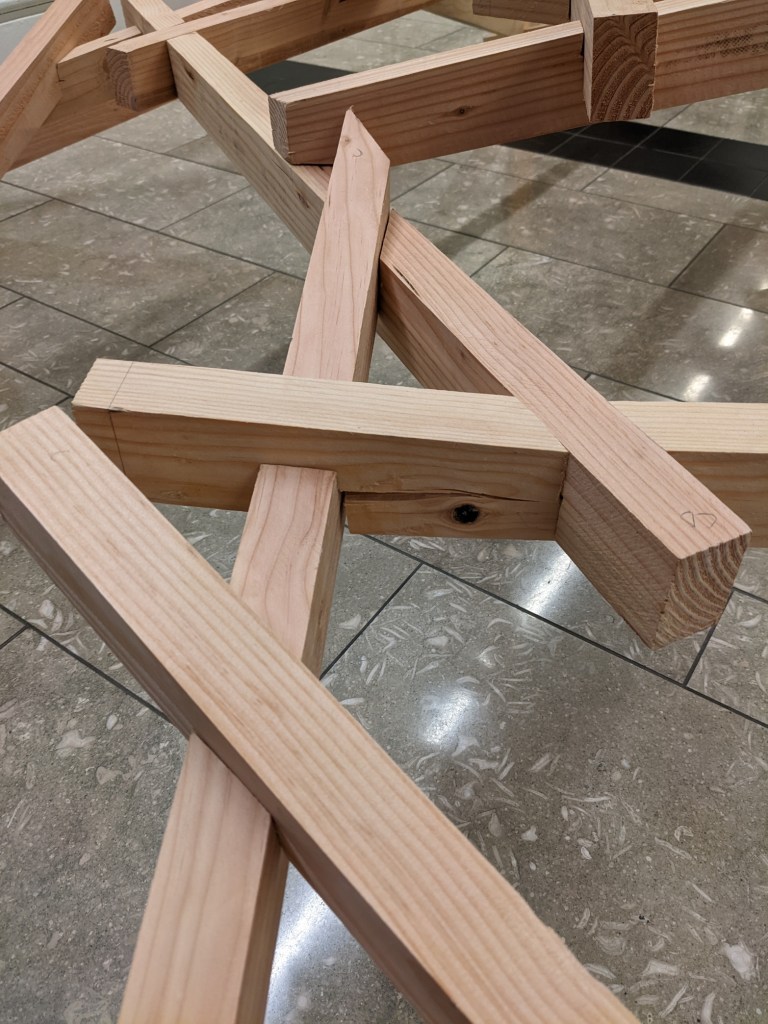
Structurally we tested point loads with MPP and Timber materials in with Karamba inside grasshopper but due to constraints we had to fabricate our final out of 2×6 douglas fir which was ripped down to 1.5″x2.5″. Walking on the structure showed us interesting results as standing on the top ring displaced the structure much less than standing on the lower rings. This was likely due to the fact that standing on the top ring concentrates the load more centrally before transferring it down the frame where as standing on the bottom as shown in the picture below localizes the stress much more. Another critical finding was that when using standard lumber it obviously has knots but we needed to place those knots on the compression side of the member which takes much more time and may be impossible in some cases but the structural repercussions are huge if you place a knot on the tension side. We found this out the hard way after splitting the wood at one of the notches from walking on the bottom ring, which you see below. This was a result of the aforementioned problems where pressure was localized and there was a knot on the tension side. You can see the knot that caused the split in the bottom left of the photo, but it has not split yet.


Leave a comment