Dome example

These images show how to ensure that support and load points are on a mesh used as a Karamba shell element. They build on Jeana Ripple and team’s UVA 1-2 Surfaces as Shell example. Download the Rhino and Grasshopper domedemo and images.

A few keys to success.

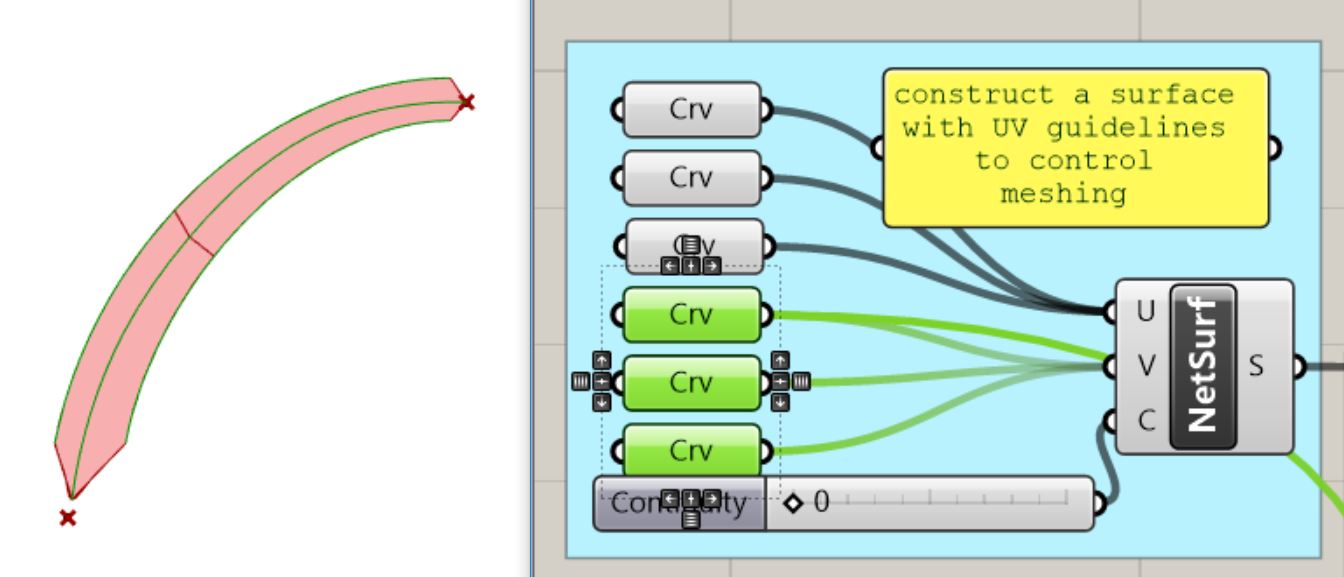
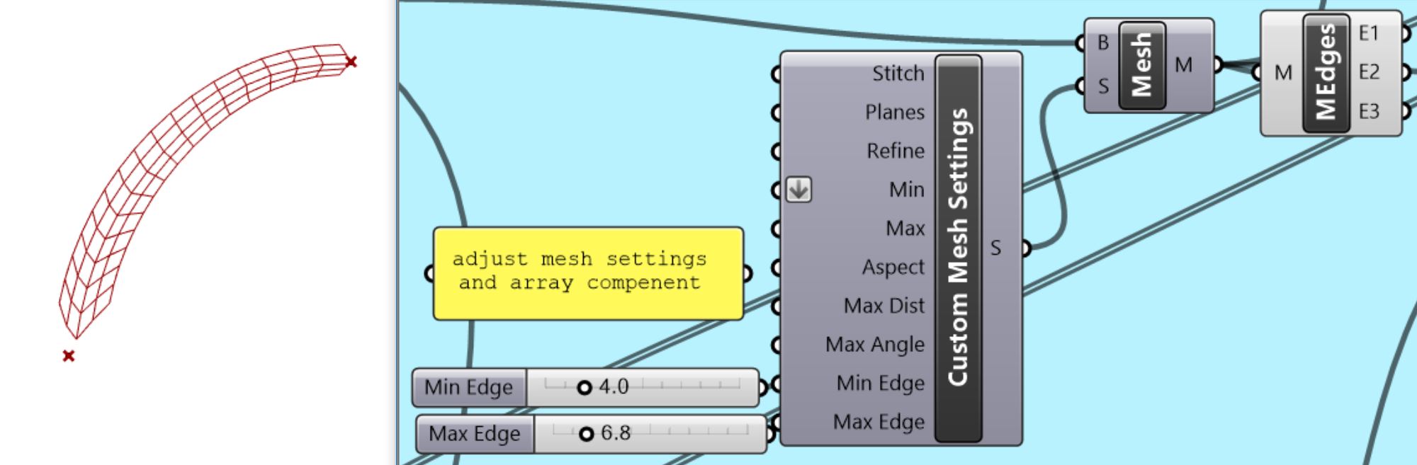
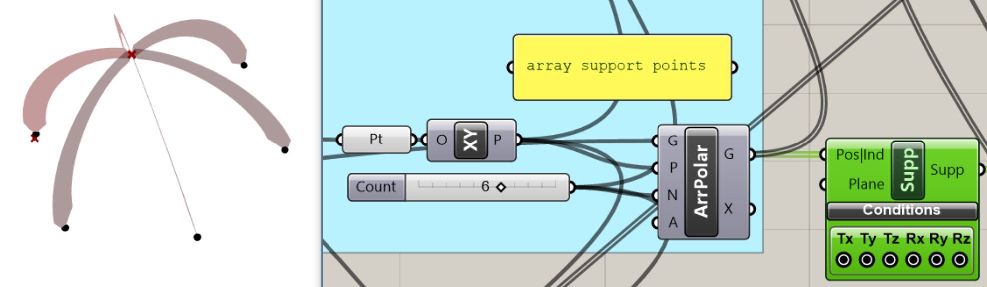
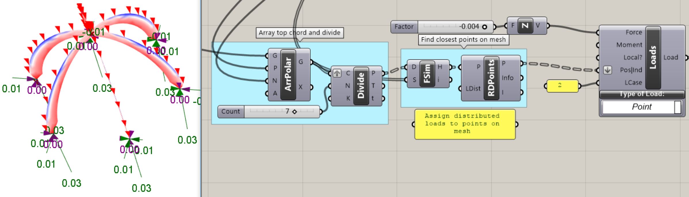
  • Make sure all the supports and loads are targeted to points of the Mesh elements. You can construct your own mesh with Curve Network surface. Use the Find Similar Member (FSim) and compare the desired locations to all the points of the mesh.
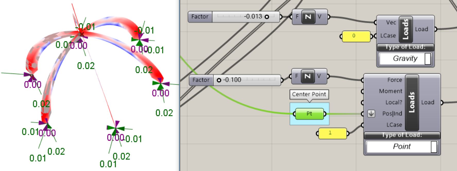
  • Make sure your units are correct. I mistakenly thought the UVA 1-2 InputSurfacesAsShell was in feet. It is in Meters. If you use it, make the forces much smaller. For example, the Mesh load needs to be about 50 times smaller (Kips/ft2 vs. Newtons/meter2).
  • The Line to Beam component only takes straight line segments, so use Line-Line intersection to divide long lines, and Divide rounded curves to find vertices for Polylines, which need to be exploded. (this is in the examples.)
domedemo1 To generate structural elements from free-form shapes, it helpes to construct a UV curve network that gives structure to the mesh.
 domedemo2 Setting the minimum and maximum length for the mesh segments in Mesh Options controls the mesh appearance.
domedemo3  The members should be arrayed around a point on the mesh
 domedemo4  Generate all the non-redundant points for both the original mesh (to get the center point for the array) and then the multiple arrayed meshes.
 domedemo5 Use Find Similar Member to search through the original mesh points to generate a new support point and a new center point (for arraying).
domedemo6  The found point can be arrayed and input into the Karamba supports module.
 domedemo7
 The center point can be loaded as a load case.
domedemo9
 For a distributed load, divide the top curve and then find the closest mesh points.
domedemo9a-crop  Use Model View and Shell View to see aspects of the analysis
 ribdome-mesh-settings2  See the Domeshell.gh example to understand how adjusting Mesh Settings (Custom) can change affect the structural result. A base Hoop ring was added to reduce outward thrust.
 ribdome-mesh-settings
24 supports are located at the intersection of the naked edge vertices, and 24 ribs are used.

Leave a Reply

Fill in your details below or click an icon to log in:

WordPress.com Logo

You are commenting using your WordPress.com account. Log Out /  Change )

Facebook photo

You are commenting using your Facebook account. Log Out /  Change )

Connecting to %s

Website Powered by WordPress.com.

Up ↑

%d bloggers like this: